Diaphragm Classes

Diaphragm Classes Class 1A

Class 1A

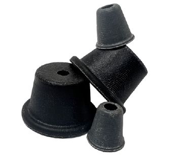
The Class 1A Bellofram Rolling Diaphragm includes “O”-Ring type bead around the entire circumference of its mounting edge. It is designed for installations requiring minimum outside flange diameter.

This construction eliminates the need for wide flanges, and in some cases, also eliminates the need for flange bolts or flange studs. It requires no perforations or bolt holes through the flange of the diaphragm.

As in other top hat diaphragms, the Class 1A diaphragm requires inversion upon installation and a curved lip retainer is suggested to prevent the piston corner radius from returning to its “as-molded” shape.

In some special designs the Class 1A diaphragm can be provided as a pre-convoluted style with a permanently molded convolution. This pre-convoluted design is easier to assemble. However, it does have the small spring gradient and centering effect which is present in other pre-convoluted designs. A flat retainer plate can be used to retain the head portion of pre-convoluted Class 1A diaphragms.

The cross-sectional area of the bead groove and the hardware for retaining the bead should be equal to the cross-sectional area of the Bellofram bead itself. The corners of the groove should be machined square with minimum fillets. These practices are recommended to provide best retention of the bead without over stressing the elastomer and fabric in the bead. If the groove area is too small, it will cause excessive compression on the elastomer and subsequent damage to the rolling diaphragm. It is recommended that this design be used where differential pressures do not exceed 150 psi.

Class 1A
DC 1.00 to 2.50 2.51 to 4.00 4.01 to 8.00 8.01 and up
H As required to yield design stroke (See standard size tables and Note 2 below.)
DC Tolerances on DC and DP are ± .010" pe r inch of diameter but the tolerance will be no less than ±.010" or greater than ±.060"
DP
WH .020 ± .005 .030 ± .005 .035 ± .005 .045 ± .007
Wsw .017 ± .003 (Code “C”) .024 ± .004 (Code “D”) .035 ± .005 (Code “F”) .045 ± .007 (Code “H”)
(Code “H”) .025 Max. .025 Max. .035 Max. .040 Max.
A .025 Max. .035 Max. .040 Max. .056 Max.
B .025 Max. .035 Max. .040 Max. .056 Max.
E 1/16 R. 3/32 R. 1/8 R. 1/8 R.
F 1/32 R. 3/64 R. 1/16 R. 1/16 R.
WB Dia. .121 ± .005 .151 ± .005 .242 ± .010 .242 ± .010

NOTES:

  1. This radius is not the piston radius since the head corner will be inverted at assembly.
  2. Height should not exceed the bore (DC). Tolerance on height to be no less than ±.015” per inch of height.
  3. This “V” rib is for diaphragm processing only. It may not appear on all diaphragms. It is not functional and need not be completely filled. Rib is normally on rubber side of diaphragm.
  4. Number, size, spacing and location of “V” ribs may be modified to suit specific beads, or may be left off altogether.
  5. Trim tolerances Hole Diameter OD Trim Diameter Tolerances 0-1.00” ±.010” 1.01-3.00” ±.015” over 3.01” ±.020”
  6. Dimensions and tolerances pertain to Bellofram Rolling Diaphragms as manufactured and not to dimensions and tolerances of mating parts.
Request a Quote

Your Satisfaction is Our Focus!

Thank you for completing this form. Your interest in our products & services is highly valued, and we're excited to be considered for your needs. Rest assured, we will carefully review the information provided to offer a tailored solution. Our experts will work diligently to ensure you receive a timely and accurate quote. Should you have any questions or need further assistance, please feel free to contact us. We eagerly await the opportunity to serve you.